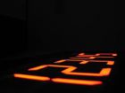
Big clock
 This bigclock is actually not a clock, but a 6 digit 7-segment universal display. Each segment on each
digit can be controlled individually to enable the user to build their own characters. The display is
controller through a serial interface (9600 bps) with a PC.
This bigclock is actually not a clock, but a 6 digit 7-segment universal display. Each segment on each
digit can be controlled individually to enable the user to build their own characters. The display is
controller through a serial interface (9600 bps) with a PC.The 6 segments are multiplexed to reduce driver electronics. A ULN2804 driver is used as low-side driver and discrete transistor driver is used as high-side driver. The high-side drivers are controlled by a simple 4022 counter. The steering signals of the counter are level converted with 2 transistors. The voltage of the high-side drivers and thereby the peak current through the segments, can be controlled by a potmeter and is created around a LM317.
A microcontroller (Atmel AT90S2313) is used to translate the commands from the PC into a multiplexed signal. It is even possible to face from one string to the next. This is all done by the firmware in the microcontroller, so the software on the PC has only to send the characters that should be displayedonce and set a fadetime. The firmware sends a OK signal if the fade to the next string is completed.
The clock was used as a count down timer to show the number of seconds till the 70th birthday of the Student Society of Applied Physics.
Schematics and PCB
The schematics for the big clock can be downloaded in Adobe Acrobat format:Big clock schematics (schematics only)
Pictures
 |
 |
 |
 |
 |
 |
 |

