Audio DAC Control
 This controller is used to control a self-built High-end Audio DAC (using an existing design by Twisted Pear Audio).
This control unit has the following features:
- Select channel and switch mains power
- Full control by both 2 rotary encoders AND remote control (RC5)
- Display shows currently selected channel as text (8 characters)
- Display must slowly fade to low intensity when not used
- Easily extendable in the future
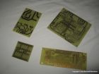
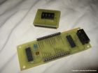
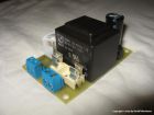
The controller consists of 3 seperate PCBs:
- Main board (housing the Atmel AVR atmega8 microcontroller
- Display board (8 alfa-numerical characters
- Supply board (+12V standby supply + 230V mains relay to switch the power to the rest of the unit)
NOTE: The PCB layout in the documents below are a newer version than the PCBs shown in the pictures.
- An error in the layout of the Main board is fixed
- The Display board is reduced from 2 to 1 board
Schematics and PCB
Main board (schematic + PCB)Display board (schematic + PCB)
Supply board (schematic + PCB)
Pictures
 |
 |
 |
 |
 |
 |
 |
 |
 |
 |

