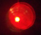
Quadrature sensor
 A quad(rature) sensor is a photo-sensitive device that can measure very small displacements of a light
spot on the sensor. The sensor itself consits of 4 photo-sensitive semiconductors. Since the signal
from this sensor is very small, the signal must be amplified many times. To decrease the noise, low-noise
opamps are used for this.
A quad(rature) sensor is a photo-sensitive device that can measure very small displacements of a light
spot on the sensor. The sensor itself consits of 4 photo-sensitive semiconductors. Since the signal
from this sensor is very small, the signal must be amplified many times. To decrease the noise, low-noise
opamps are used for this.To derive the X and Y displacement signal, the amplified signals must be added and substracted in some way.
The first version of the sensor did not perform very well. The signal dit not only depend on the position of the spot on the sensor but also on the shape of the spot. To investigate the problem, a computer simulation of the sensor was made. This proved that another measurement method would improve the performance of the sensor much.
Me and a friend of me have designed and built a sensor that is able to do this with very low noise levels. The primary/secondary winding parasitric coupling in a transformer would certainly increas these noise levels. Therefore, the sensor was powered by 2 9v batteries. Since the power consumption of the electronics is very low, only 2 batteries were nessesary to power the electronics troughout the whole project.
All parts (including the batteries) are placed in a metal housing to keep the noise away from the sensitive amplifiers and sensor. The leads to the 4 input amplifiers are kept as short as possible (although a shorter path is possible when a special PCB is designed). Since also lowpass filters are included at the inputs of each second stage, no coaxial cable was needed for very high noise immunity.
Schematics and PCB
Quadrature sensor (schematics only)Pictures
 |
 |

